
After using Altium for years, I finally gave KiCAD a proper try. I wasn’t expecting much, open-source tools, but KiCAD proved me wrong. It’s powerful, flexible, and surprisingly well thought out.
That said, moving from Altium’s highly structured world to KiCAD meant I had to rethink one of the most critical parts of my workflow: Library Management. While KiCAD does things differently, it turns out there’s more than one good way to manage your symbols and footprints—as long as you do it intentionally.
Approach 1: The Generic Symbol Shortcut
This is the fastest way to get things done and the easiest to regret later. You use a single generic symbol for a component type, like a universal resistor or capacitor. Need a 10 k resistor? Just change the value. Need a 33k? Type it in. Same symbol, different value. It’s fast, flexible, and honestly feels kind of clever the first time you do it.
Fast? Oh yes.
Safe? Ehh… not always.
I’ll be honest: when I first saw this method, I thought, “This feels like using a pinset as a screwdriver. Technically it works… until it doesn’t.”
The moment you want to add a voltage rating, a tolerance, or even a supplier field, suddenly you’re stuck editing every instance by hand. It’s fine if you’ve used the part twice, but what about fifty times? Now you’re playing Find-the-Difference with your own schematic 🤣.
And then it gets worse.
You think you’re just updating a footprint in the library and suddenly, half your values vanish. That 100 nF decoupling cap becomes a mysterious blob labeled “C?” and you’re left staring at the screen wondering:
“What even is this thing supposed to be?”
At that point, debugging turns into archaeology. You’re not just fixing a mistake, you’re excavating your own design using nothing but mysterious rectangles and your memory. It brought back memories from when I first learned PCB design, my schematics were full of floating values and symbols like Cap_0603 that looked more like riddles than components.
This method is fine if you’re building a quick prototype for a weekend project or if you enjoy living on the edge.
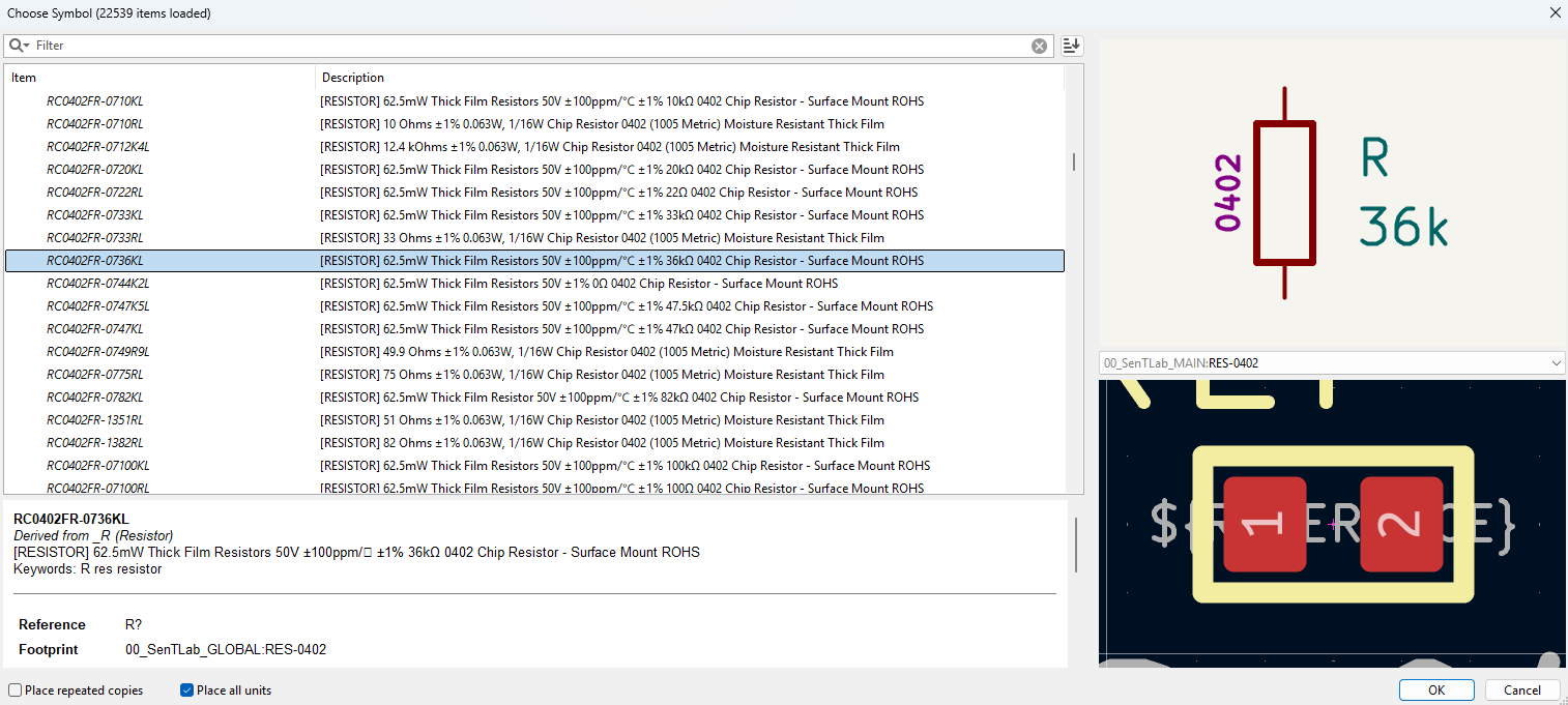
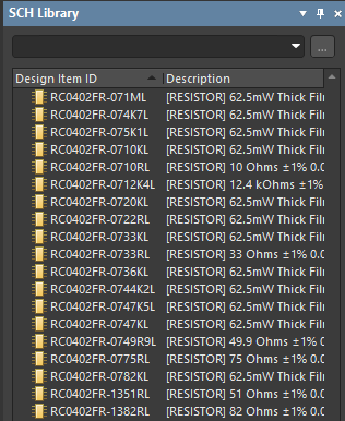
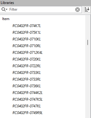
Approach 2: One Symbol One Component
This is the method I used in Altium, and it’s still the one I trust when things get real.
In this approach, each specific component gets its own symbol. That means a 100R 1% resistor has one symbol, and a 100R 5% resistor? Of course it has another. Even if they share the same footprint, the symbol includes all the details, value, tolerance, voltage rating, part number, supplier, you name it.
“Whoa, overkill.”
But to me? That was sanity. That was structure. That was knowing I wouldn’t accidentally put a 16V capacitor in a 24 V rail
Sure, your symbol library will grow.
Your parts list will look longer than your grocery list.
And yes, you might start to feel more like a librarian than a designer.
But you know what? That’s a good thing.
You never accidentally replace a 1% resistor with a 5% one.
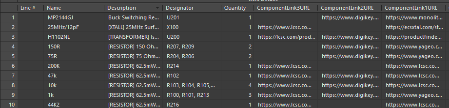
You won’t have “mystery resistors” sneaking into your BOM.
And when you come back to the project months later, you won’t be playing detective. You’ll know exactly what’s on your board and why.
And if you’re a beginner reading this: do yourself a favor, use this method and just thank me later.
Yes, it takes time to build the library.
Yes, you might feel like you’re getting a PhD in resistor taxonomy.
But trust me, your BOM will thank you. Your PCB will thank you. Future-you will definitely thank you.
Approach 3: The Hybrid Method
Best of Both Worlds… If You’re Careful
This is the middle-ground strategy and probably the most realistic one for fast-paced projects.
You start your schematic with generic placeholder symbols so you can focus on design without getting bogged down in part selection. Then, once things are stable, you go back and swap in proper components from your structured library.
It’s like prototyping with sticky notes and replacing them with printed labels once the design is ready.
For example, I had a project with a crystal oscillator that needed load capacitors. I didn’t know the exact values yet. I was still figuring out the stray capacitance of the layout, so I just dropped in a C_LOAD placeholder. Generic symbol, generic footprint, no value. Just vibes.
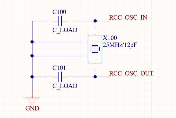
Once I had the measurements and calculations, I replaced C_LOAD with a proper 18 pF, 5%, 50 V cap from my library. Part number and all. Clean and correct.
This method gives you speed during schematic capture and accuracy before production. But because it’s a hybrid, it works best if you treat it as temporary.
Tips for surviving the hybrid life:
- Keep placeholders to a minimum.
- Replace them early, not at the last minute.
- Build your structured library as soon as you have the time.
Final Thoughts
Personally, I lean structured. I like knowing my capacitor won’t mysteriously turn into an LED when I update the footprint. If you want your projects to scale, collaborate smoothly, and stay readable six months, years from now.
Call it strict
Call it structured.
But don’t call me when your schematics turns into a riddle 🤣.
Bonus: Want to see how I organize my KiCAD libraries, symbol naming, or how I manage variants? I’m happy to write a follow-up. I’ve made the mistakes so you don’t have to 😄. Let me know in the comments or if you’re feeling brave, share how you manage your own KiCAD library.